| View previous topic :: View next topic |
| Author |
Message |
nj111
Just got MTs
Joined: 15 Dec 2010
Odometer: 166
Location: Forest of Dean
|
 Posted: Mon Feb 24, 2014 5:46 pm Post subject: Posted: Mon Feb 24, 2014 5:46 pm Post subject:
|
 |
|
A small amount of agitation is needed to shift the bubbles off the surface of the work, just a few air bubbles rising around the part will be enough.
You could use a fish tank aerator but I use an airline off the compressor shut right down through a restrictor valve to almost nothing.
This agitation speeds the process up by around 50%, without it the part could be in the acid 100 minutes or more.
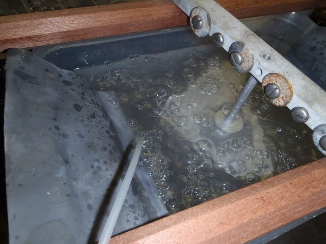
The acid needs to be between about 18 and 25 degrees C and the electrical current does warm it up.
If it gets too hot the process slows, then you either stop for a while or immerse a hose in the tank
with cold water running through it or sit the acid tank in another tank of water to take some heat away.
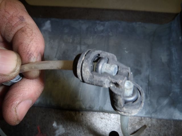
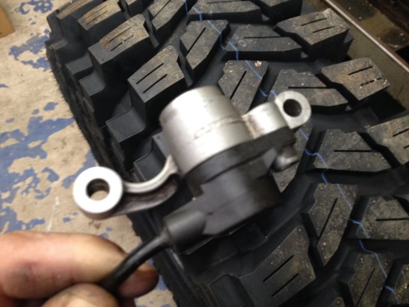
This shows how aggressive the sulphuric acid is, there's nothing much left of this airline fitting.
I forgot to rinse it last time it had been in the acid.
Would have thought plastic should have been ok here?
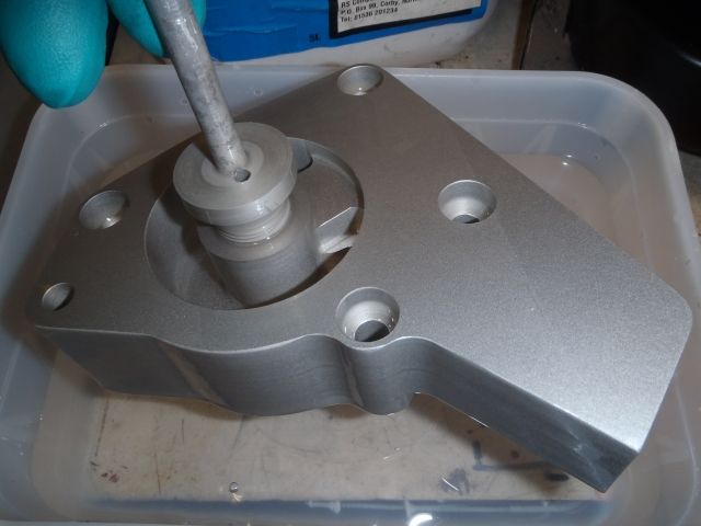
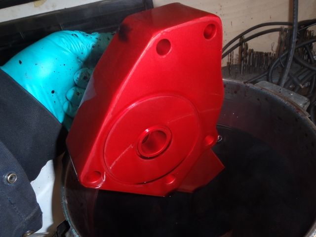
Here's the part just lifted out of the acid bath. Looking good but not fully anodised yet.
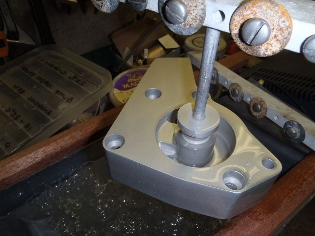
After this the part is swilled off in two separate dip tanks, that's de ionised water at £4 / gallon from motor factors,
or what comes out of a dehumidifier is perfect, but not tap water.
Using two wash tanks ensures that no acid is left on the part before applying the dye.
The anodised layer has microscopic pores and if you want the part coloured the idea is the dye will go into those.
That's why a dye with particles smaller than the pores is essential, so not any old dye will work.
Some people have found that clothes dyes and inkjet inks are ok but I reckon it's best to spend £20 on a litre of the proper dye
which will last for years.
(Frost Auto Restoration) and this is a concentrate so is then diluted with several litres of de ionised water.
Now with the dye heated up in the microwave, max 50 deg C, no hotter, the part is swished around for a few minutes
until it visually doesn't take any more dye, ie. it gets no darker in colour.
If you heat the dye on a hot plate instead of microwave you must keep stirring and have only a gentle heat
or it goes lumpy in the bottom of the pan and ruins the dye, that doesn't happen in the microwave.
The dye now is now into the pores but the pores are still open.
There are ways to seal the pores which are probably quicker and involve chemicals
but amazingly this can also be done properly by immersing in boiling water or steam for about 30 minutes.
Yep, just put the dyed bits in a saucepan of boiling water. (Strongly advise: Old saucepan from boot sale and done when she's out).
This causes the pores to close up over the dye particles. The dye is then trapped. Sounds unbelievable but it does the trick and it is a permanent irreversible process.
This is why we didn't want the dye too hot, as it could have started to seal the pores too early.
Even if the part is not dyed the pores must be sealed over.
This is a chemical change to the surface from Aluminium Hydroxide to Hydroxide monohydrate,
chemists here will I understand that, personally don't care what they call it so long as it's done.
If it goes wrong, anodising can be chemically stripped by a strong mix of Sodium Hydroxide (Drain cleaner granules & water) then have another go.
It will need to be a much stronger mix than the etch mix used earlier, but same stuff.
So it's possible to strip existing anodised parts that look a bit knackered and re-do them.
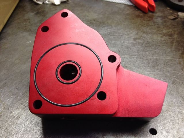
Anyhow it looks cool now.
Why not do this to the sump? Well that's maybe 600 square inches surface area so would need 60 amps applied for an hour, and I figure that may get the 10 litres of sulphuric I have available a bit on the warm side.
Last edited by nj111 on Wed Sep 02, 2015 12:46 pm; edited 3 times in total |
|
| Back to top |
|
 |
|
|
nj111
Just got MTs
Joined: 15 Dec 2010
Odometer: 166
Location: Forest of Dean
|
| Posted: Mon Feb 24, 2014 5:49 pm Post subject:
|
|
|
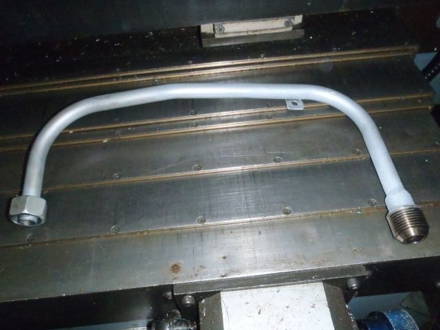
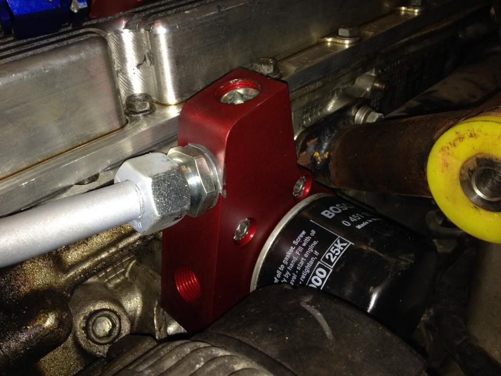
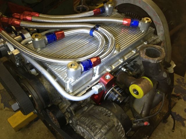
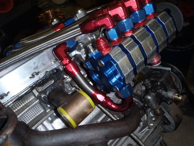
I used 15mm seamless hydraulic tubing (steel) for most of the pressurised pipe run around the front of the engine.
It's more compact, bends well with a plumber's copper pipe bender to a tight radius and is less susceptible to damage than a flexi.
A stock compression fitting was used at one end and a custom turned one at the other to adapt this to a short piece of AN12 braided hose - just long enough to allow the pump's belt to be tensioned.
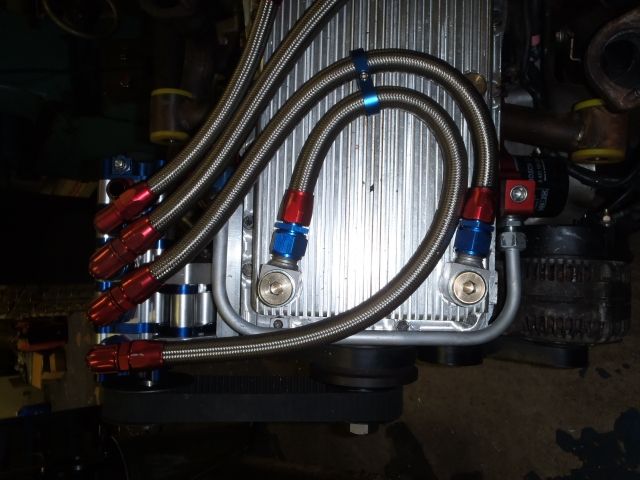
I really hope that's the dry sump done, started July 2012 and closed the lid on it Feb 2014.
Fingers crossed it all works and that the untested 2nd hand oil pump proves good.
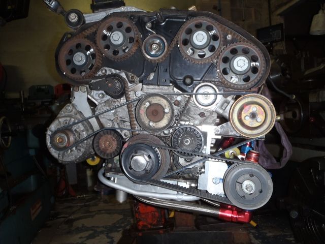
The scavenge hoses and fittings added 40mm to it's height so the engine is now around 580mm tall right from the underside of all the hoses to the top of the induction pipes.
That's about the same height as the Suzuki 1.3 in our SJ trialler. It's about 60mm longer than the SJ motor but of course a fair bit wider.
No idea how that size compares to a Suzuki V6,
anyhow whilst I also respect that motor, it's been done before and with the Suzi or other V6's you don't get the awesome sound of an Alfa V6.
No idea who's GTV this is (apart from silencer I'd say it's pretty stock) our SJ should make a similar noise. Also, these motors are pretty strong on torque.
http://www.youtube.com/watch?v=DZYD4vYZkEU
Looking at everything made right since the start, I reckon now that I have it all figured out and drawn up on CAD, if I did it again I could get to this stage of the build in 120 hours or so. (Uninterrupted!)
Last edited by nj111 on Tue Aug 12, 2014 3:30 pm; edited 1 time in total |
|
| Back to top |
|
|
arreff77
Articulating

Joined: 03 May 2009
Odometer: 992
Location: porthleven cornwall
|
| Posted: Mon Feb 24, 2014 8:15 pm Post subject:
|
|
|
I love watching this build. Sir you are building a thing of true beauty.
__________________________________
welcome to the dark side, we have cookies. |
|
| Back to top |
|
|
nj111
Just got MTs
Joined: 15 Dec 2010
Odometer: 166
Location: Forest of Dean
|
| Posted: Mon Feb 24, 2014 9:16 pm Post subject:
|
|
|
| arreff77 wrote: | | I love watching this build. Sir you are building a thing of true beauty. |
Thank you! I hope it turns out that way, plenty of ideas still to come.
There's been enough time to think of them...
|
|
| Back to top |
|
|
Xpajun
Mud Obsessed

Joined: 22 Sep 2008
Odometer: 3245
1988 Mitsubishi Shogun
|
| Posted: Mon Feb 24, 2014 10:12 pm Post subject:
|
|
|
Thank you for the in depth review of anodising - enjoyed reading that...
I think one of the things I like about this build is the pure engineering that you pour into it - even if it never gets finished (and I'm sure it will) what you have done so far is a thing of true beauty, and what you do to it in the future will only enhance that beauty
| nj111 wrote: | | plus some equally aggressive caustic soda i.e. Sodium Hydroxide (oven cleaner / drain cleaner) |
Back in my factory days we used to use caustic soda to clean brass inserts before they were moulded into plastic parts - we had a bag of caustic soda, about 25 or 50 pound size. We used to use a small saucepan to scoop it out, anyway someone left the saucepan half buried in the caustic soda one day, so the next time we came to use it ,grabbed hold of the handle and pulled it out expecting a saucepan half full of caustic soda...
Yep you guessed it, the saucepan was aluminium, all that came out of the bag was the half of saucepan that wasn't in the caustic soda - the rest had disappeared 
| nj111 wrote: | This shows how aggressive the sulphuric acid is, theres nothing much left of this airline fitting.
I forgot to rinse it last time it had been in the acid.
Would have thought plastic should have been ok here? |
Those fittings are made of Delrin (acetal resin) which does not stand up to acids (even mild ones) very well - one of the many reasons we don't use Delrin in the manufacture of our body lift kits
|
|
| Back to top |
|
|
nj111
Just got MTs
Joined: 15 Dec 2010
Odometer: 166
Location: Forest of Dean
|
| Posted: Mon Feb 24, 2014 10:55 pm Post subject:
|
|
|
I like that aluminium saucepan story!
Thanks also for the explanation of the disappearing airline fitting, didn't know those were Delrin. Underlines the point of having to know your materials in whatever you do.
I find the more I look into things, the more I realise how much I don't know.
One other thing about anodising, I forgot to say that it's an insulator. Maybe only a thou thick but a pretty good insulator. Check it out with a Megger and see.
This means you can't weld previously anodised material,and it also means the part that's hanging in the acid bath wants to insulate itself from the bit of wire it's hanging from during the process. Commercially I'm sure that's not even an issue, but it sometimes catches me out.
|
|
| Back to top |
|
|
Stal1878
Mud Obsessed

Joined: 02 Mar 2010
Odometer: 3320
Location: Somerset
1990 Daihatsu Fourtrak
|
| Posted: Wed Feb 26, 2014 12:08 pm Post subject:
|
|
|
| nj111 wrote: | | Stal1878 wrote: | | no doubt a silly question, but where does the metal go from whatever you are spark eroding? |
No, that's a good question.
It's disintegrated into very fine particles, and mixes with the EDM fluid.
What came off here looked like clouds of black soot mixed with the EDM fluid that the part is immersed in. The problem is those microscopic particles conduct electricity so they need removing from between the electrode and the workpiece, otherwise the process will slow right up and basically stop because the machine keeps a constant gap between the electrode and work.
To do this the work piece must be flushed continuously, but gently, by jets of EDM fluid. Often it helps to flush through the centre of a hollow electrode, especially for deep work. There's an elaborate filtration system on the machine to remove this debris from the EDM fluid,but eventually the fluid does go black and needs changing. At the moment it's still nice and clean so I can see what's going on. Also there is a fire risk so the correct fluid should be used, rather than say kerosene. There needs to be a couple of inches of fluid above the work piece to reduce that risk.
A few strong magnets placed here and there also catch some of the eroded material if it's a ferrous material.
On the home made machine I used a suds pump and a couple of diesel fuel filters to catch the muck, that works ok as they do filter to a very fine size. The filters on the commercial machine are massive by comparison though- maybe 20 or 30 times the size of a fuel filter. |
Thanks very much for explaining this, really interesting 
Just going to read the updates now 
|
|
| Back to top |
|
|
Stal1878
Mud Obsessed
Joined: 02 Mar 2010
Odometer: 3320
Location: Somerset
1990 Daihatsu Fourtrak
|
| Posted: Wed Feb 26, 2014 12:29 pm Post subject:
|
|
|
Wow, great guide on the anodising, thanks very much for putting that up 
Everything you do and own is top quality, even your battery charger is top class
|
|
| Back to top |
|
|
nj111
Just got MTs
Joined: 15 Dec 2010
Odometer: 166
Location: Forest of Dean
|
| Posted: Fri Feb 28, 2014 9:32 am Post subject:
|
|
|
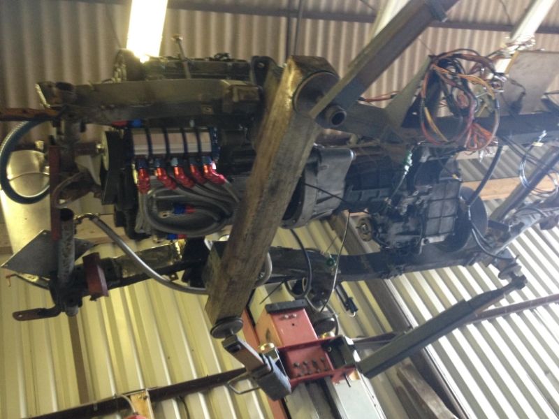
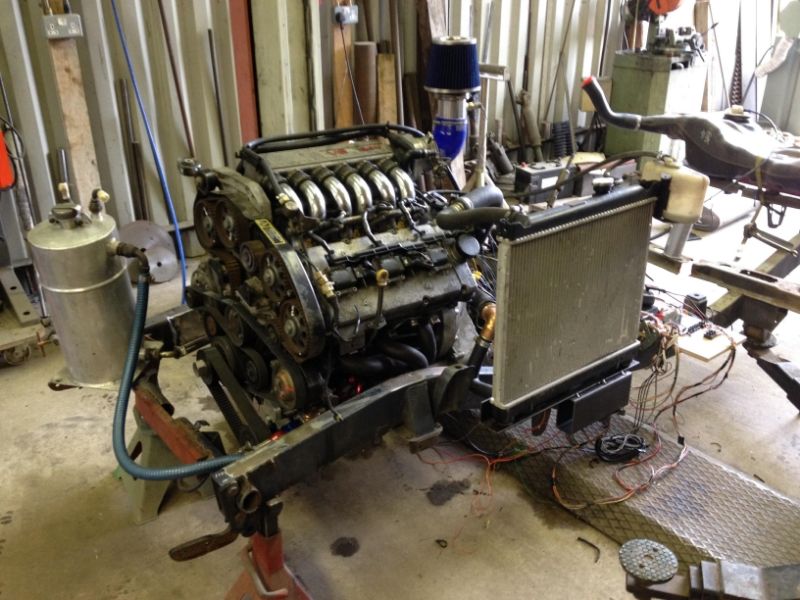
After a few late nights spinning up various custom parts and adaptors she's in there.
Axles temporarily tacked in place at full compression and wheelbase still to be decided.
Those wheels are looking too small, I can feel 37" treps coming on at some point,so will build to acccomdate.
Next: rig up temporary oil tank & get her running.
There's a parallel project running for a couple of months so my time on this will be divided in half.

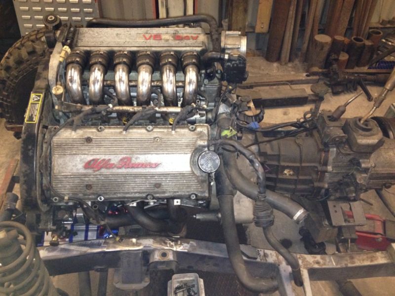
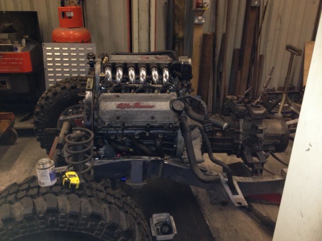
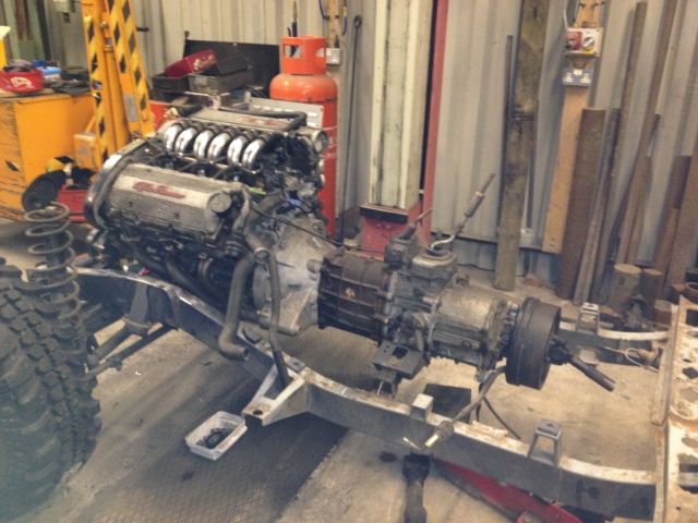
This shot shows how low the motor now sits. The way it's canted over helps due to the extra couple of inches clearance over the diff and front propshaft.
It's the same angle it was at in the fwd Alfa 156 so the headers are sitting pretty square and can remain unaltered.
|
|
| Back to top |
|
|
Stal1878
Mud Obsessed
Joined: 02 Mar 2010
Odometer: 3320
Location: Somerset
1990 Daihatsu Fourtrak
|
| Posted: Sat Mar 29, 2014 5:06 pm Post subject:
|
|
|
Looks ace in there mate
Whats the other project though?
|
|
| Back to top |
|
|
|
|
jon.g1
Articulating

Joined: 07 Nov 2007
Odometer: 753
Location: Taunton, Somerset, UK
|
| Posted: Sat Mar 29, 2014 9:17 pm Post subject:
|
|
|
Looking awesome, we need a 'LIKE' button on here
__________________________________
If you make it idiot proof...
They will make a better idiot!
Project Zulander |
|
| Back to top |
|
|
Twiss
Mud Obsessed

Joined: 18 Feb 2008
Odometer: 6438
Location: Birkirkara, Malta
1993 Suzuki Samurai
|
| Posted: Sun Mar 30, 2014 10:42 am Post subject:
|
|
|
Such an awesome build!!!
When you finish this I would gladly drive 3 hours to see it!
__________________________________
Twiss
'95 Samurai 416 16v
'92 Maruti Gypsy MG410
www.suzukiclubuk.co.uk |
|
| Back to top |
|
|
nj111
Just got MTs
Joined: 15 Dec 2010
Odometer: 166
Location: Forest of Dean
|
| Posted: Mon Mar 31, 2014 4:02 pm Post subject:
|
|
|
| Stal1878 wrote: | Looks ace in there mate
Whats the other project though? |
Thanks all for your positive comments.
Negative ones also welcome if you can see something is not right I'd like to know!
Since you asked, Stal1878 the other project is a lot of work, has to be done by end of July.
A rebuild on this, one of 3 Field Marshall Based Locomotives sold in the UK 64 years ago.
They were rated to pull 160 ton on the level.
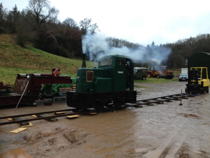
Right now it's an 8 ton pile of bits and many problems to overcome including Frost cracked block so rebore on another block going on here:
(Wish this awesome Russian Borer was in my shed, big thanks to Dave for a cracking job there.)
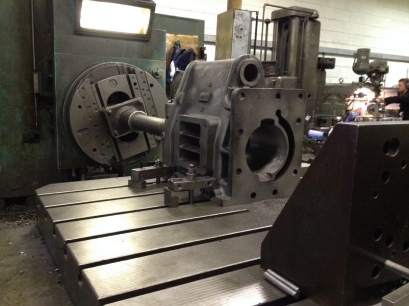
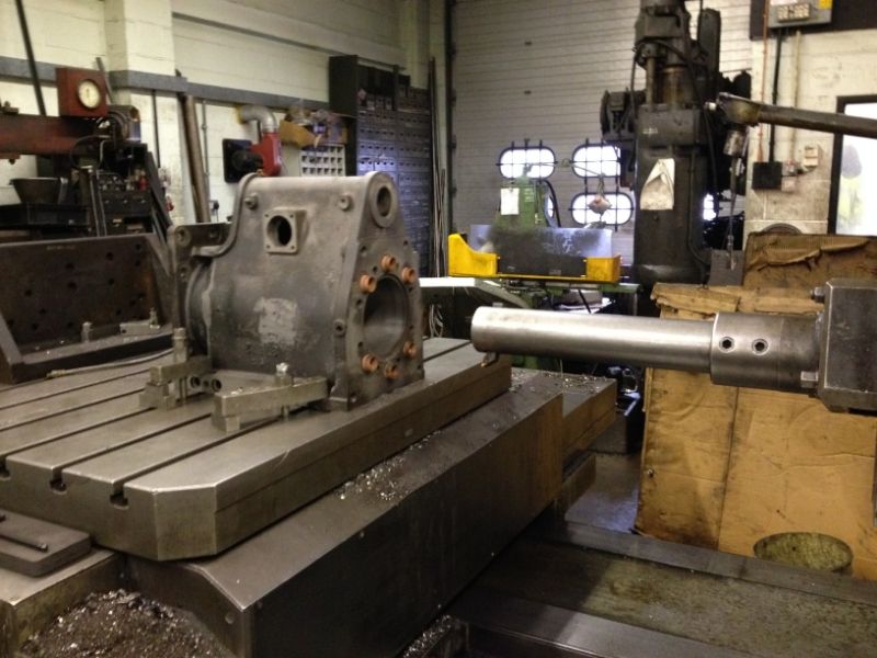
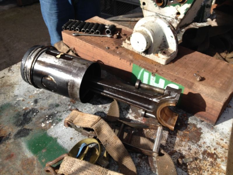
But reboring means the original iron piston is too small so gotta turn a new one and it's 6.5" diameter 13 kgs weight.
If anyone wants to see the thing (hopefully finished and running on track) the deadline is Welland Steam Rally 25th 26th 27th July.
Club's 50th Rally and It's Marshall year there will be dozens of them there.
So that's why Alfazuk got to wait until August till I get back on with it.
Not enough hrs in the day! (All done in spare time and weekends)
Last edited by nj111 on Tue Aug 12, 2014 3:32 pm; edited 2 times in total |
|
| Back to top |
|
|
cynic-al
Mud Obsessed

Joined: 14 Nov 2006
Odometer: 6062
Location: scunthorpe
1989 Suzuki SJ
|
| Posted: Mon Mar 31, 2014 6:23 pm Post subject:
|
|
|
They're currently trying to get something very similar going near me, they're trying to get the old crowle and Thorne moor peat railway going again as a preserved railway. All interesting stuff
__________________________________
I know enough to be dangerous. |
|
| Back to top |
|
|
nj111
Just got MTs
Joined: 15 Dec 2010
Odometer: 166
Location: Forest of Dean
|
| Posted: Mon Mar 31, 2014 7:12 pm Post subject:
|
|
|
| Interesting, a lot of the Peat works ran on 3 ft gauge (same as this loco), very little 3ft around in UK, some in Ireland.
|
|
| Back to top |
|
|
Stal1878
Mud Obsessed
Joined: 02 Mar 2010
Odometer: 3320
Location: Somerset
1990 Daihatsu Fourtrak
|
| Posted: Wed Apr 02, 2014 6:32 pm Post subject:
|
|
|
I like the look of that, dear little thing!
How'd your mate manage to get hold of a Russian(Soviet?), looks like a proper tool
|
|
| Back to top |
|
|
nj111
Just got MTs
Joined: 15 Dec 2010
Odometer: 166
Location: Forest of Dean
|
| Posted: Wed Apr 02, 2014 8:04 pm Post subject:
|
|
|
| Stal1878 wrote: | I like the look of that, dear little thing!
How'd your mate manage to get hold of a Russian(Soviet?), looks like a proper tool |
Proper job that Soviet borer. Boring bars up to 9" diameter. Table will also continually rotate. All recirculating ball leadscrews etc. Think they've had workpieces up to around 9 foot diameter on there. Very nice machine, but also they are exceptionally skilled at using it.
|
|
| Back to top |
|
|
Toseland
Mud Obsessed

Joined: 25 Oct 2011
Odometer: 3209
Location: cardiff
1999 Suzuki Vitara
|
| Posted: Wed Apr 02, 2014 9:37 pm Post subject:
|
|
|
that looks like an art..
worked for a company that made the aluminium crash barriers used by MIRA for the road safety tests...
we had a 33000litre tank of 65% hydrofluoric acid, heated to a lovely 62degC, that we used for etching the barrier thickness to change its crush strength in certian sections.
it broke through a crack in one of hte heater lines, on the saturday evening of a bank holiday.. ate through the fan and heater assembly on the end of the line, and approximately 20000 litres poured out of the end of the stainless line, onto the coated concrete floor below, and ate a 90foot deep, 2 foot wide hole into the ground where it was flowing slowely out and pouring to the floor..
and dissapeared..
right next to that we had anbother 25 or so thousand litres of Sodium hydroxide for neutralising the acid...... yummy
btw... i am going to start sending you orders =D
__________________________________
I live by 2 sayings:
1. The beatings will continue until morale improves
2. Pain is just Weakness leaving the body..
The feeling you get when you first smash your shaft out, is one you will never forget.. especially if you do it in front of 10 guys. |
|
| Back to top |
|
|
nj111
Just got MTs
Joined: 15 Dec 2010
Odometer: 166
Location: Forest of Dean
|
| Posted: Thu Apr 03, 2014 7:01 am Post subject:
|
|
|
| Bet the Environment Agency loved that. I feel more comfortable about having only 10 litres of Sulphuric Acid on my bench now.
|
|
| Back to top |
|
|
nj111
Just got MTs
Joined: 15 Dec 2010
Odometer: 166
Location: Forest of Dean
|
| Posted: Thu Aug 28, 2014 12:45 pm Post subject:
|
|
|
Build Restart!
That other project grew into a massive amount of work with at one time14 pallets of parts requiring my attention, and was finished 24 hrs before the deadline, but that's not a story for here.
So after 5 months break AlfaZuk has moved back into the build shed. This time it will be without interruption until completed and I'll update here as I know a few have been following from the start well over 2 years ago.
Maybe a break has been a good thing as watching 2 days at KOV recently (recommended) has not only inspired me to get it finished but like so many others I've realised I'd be better off switching to Y61 (Patrol) axles
Especially before sourcing 2 x ARB lockers, Longfields, Nitro Ring and Pinions, Six Shooter hubs etc to make the yota ones somewhere near as reliable as those from a stock Patrol.
This has been in the back of my mind for a while and it's only because I already have 2 sets of yota axles that I've not made the decision to change sooner.
It's not that LJ70 axles are weak, far from it, they'd be fine left standard with the average power plant, and the 4.88 ratio diffs are great, but unless I spend heavily on upgrade parts I'm pretty sure with 40" tyres and 220 to 250HP there would be issues from time to time.
So PM me if you need LJ70 axles they'd be the perfect addition to your Suzuki.
A growing number of crews ran with Y61 axles at KOV this year, and feedback is good, so thought I'd better do something about it before they get really hard to find.
Initially that didn't go too well. Soon found a set of axles advertised within the 4x4 fraternity, agreed to pay the asking price, was assured "they're yours, gentleman's agreement" etc but that was followed by various excuses as to why I couldn't collect and eventually the deal was off and there were no axles.
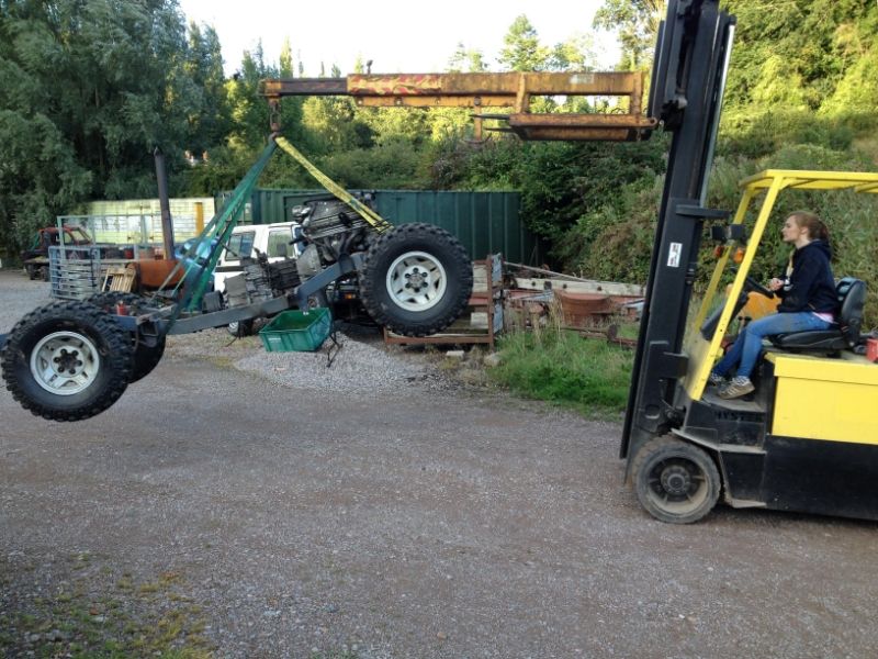
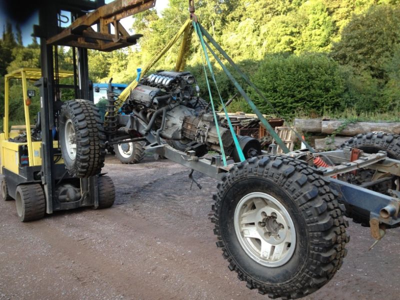
But it didn't really matter as I did it the other way, went shopping for a Y61 and it took about 10 minutes to find one. Asking price wasn't unreasonable with a fresh MOT for a year 2000 truck.
Significant road trip involved though.
Drives well and even the leather heated seats and aircon work but there's way more corrosion than on my Amazon of the same year.
I'll keep axles, propshafts, maybe rad, servo, alloys and a few other bits.

I now think this is a good way to source these axles, as I've driven it, checked it out and if parts are required chassis number is known.
When a few bits are sold the axle cost could well be less than the going rate of a pair of axles with calipers and props which as far as I can see is now £850 to £900 - if you can find them.
The plan is to retain the factory rear locker and most likely fit an ARB to the front, the other option being limited slip diff ex Terrano 2 / Maverick (rear). Apparently that works well for the money.
So that's axles sorted, but back to those later, before they go on I want to get the motor running.
Last edited by nj111 on Wed Sep 02, 2015 12:50 pm; edited 1 time in total |
|
| Back to top |
|
|
|
|
nj111
Just got MTs
Joined: 15 Dec 2010
Odometer: 166
Location: Forest of Dean
|
| Posted: Thu Aug 28, 2014 12:50 pm Post subject:
|
|
|
For a while I've been chewing over where to locate the engine oil tank and I've got reservations about having it some distance from the motor.
It would be nice right next to the pump in the front of the vehicle but that's imposing on winch space.
Regulations dictate that we can't have a gallon of hot pumped oil stored in the cab and even if we could there's little room and I wouldn't take that risk, so the tank would need to be further back - behind the rear bulkhead.
Some race cars have the oil tank at the opposite end to the motor, like 911's and Skylines but they don't operate at extreme angles for some time.
I'm thinking of this truck nose up for a while and with the tank that far back it could be about 6 feet below the engine.
Maybe that's asking a lot for the pump to perform like that? I expect it would be if it wasn't primed. Don't know the answers but it would be a shame if the engine got starved of oil just because the tank was badly positioned.
There'd also be pipe runs for flow and return which could get damaged and when parked up for some time I expect some oil will drain back to the sump (through the pump rotors),
so there'd be a delay while the oil is moved from sump to tank, then back again to the pump's pressure side through long pipe runs.
One of the objectives of this build is to keep it light (Patrol axles will not have helped that) and I noticed at KOV quite a few now run vector winch set ups. I like the idea of that.
Relocating the winch would allow the oil tank to go immediately in front of the engine, with no worries of oil starvation also saving weight. So that's most likely what will happen, leaving a decent space for an oil tank right in front of the engine.
I needed to spin the engine over to see what's happening with oil pressure and flow. To get things moving an oil tank was positioned with temporary hoses.
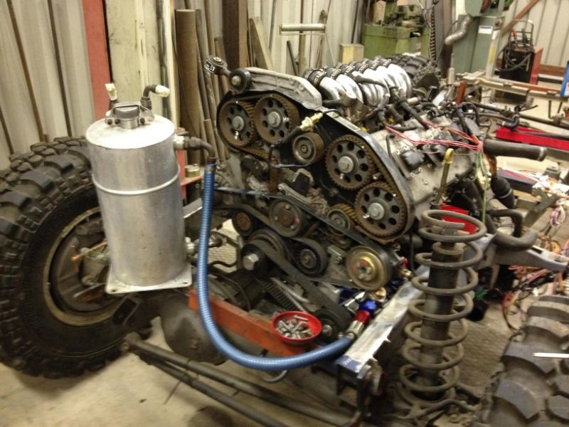
Also rigged up an oil pressure gauge to monitor the situation.
Engine, filter, pump and hoses were dry of oil but after about a minute of cranking (with 3 plugs out) this was the result.
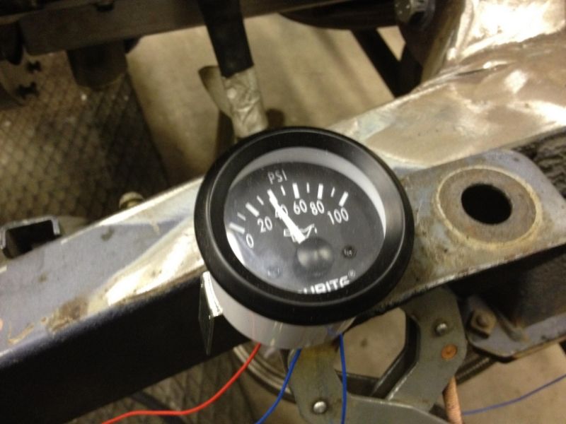
Really surprised, didn't expect 40psi from cold cranking at around 160 rpm, would have been happy with 5 psi. Also there's plenty of flow back to tank.
Looks like this pump could be run way slower than it is at the moment. May revisit that at some point as there must be loads of oil being bypassed through the scavenge rotors.
Last edited by nj111 on Wed Sep 02, 2015 12:52 pm; edited 1 time in total |
|
| Back to top |
|
|
nj111
Just got MTs
Joined: 15 Dec 2010
Odometer: 166
Location: Forest of Dean
|
| Posted: Thu Aug 28, 2014 1:17 pm Post subject:
|
|
|
That looks good enough for a trial run but there's no ECU, that's still in the donor vehicle.
It would be an option to strip the harness down, fit ignition barrel, immobiliser etc but I want to be in control of what's going on, not have it going into limp home mode when it feels like it, say during an event.
I also want to be able to switch the 2.5 motor for the 3 litre GTV motor and just modify fuel mapping - not change an ECU and immobiliser.
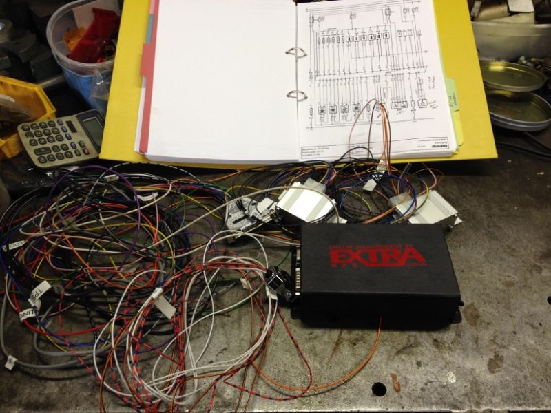
That's why I decided to install Megasquirt, a stand alone engine management system configured from a laptop.
I used a reputable UK supplier for this, (Phil at Efi Extra) it cost £480 built and tested with manuals and leads. (Edit: £380 plus £100 for two spark boxes to drive the 6 COP's) I expect these can be bought cheaper but it's new to me so I'd rather have Phil's support as needed.
If it were a Rover V8 then Megasquirt could be bought as plug and play.
Every wire is clearly labelled and the manuals are very comprehensive.
These have been used to run Alfa V6 motors and they run them well, but there's not too much info shared on the web about Alfa set ups, so it's taken a while to figure out the wiring to injectors, coil packs, and sensors.
If you know a garage with Autodata then you can print out the wiring diagrams for the entire vehicle.
Looks like it will work out neatly as there's one big plug on the back of the engine which connects all injectors and coil packs to the main wiring harness.
I cut the loom some distance from this plug to connect to Megasquirt. So for future engine changes Megasquirt just plugs into any Alfa V6 motor using the original plug. Nice and easy, that's the theory anyway.
There are various models of Megasquirt, I chose MS2 and for a V6 that allows fuelling to be semi sequential and ignition wasted spark.
My understanding at the moment is I don't need to bother with a MAF (Mass Air Flow) sensor as there's an inbuilt MAP (Manifold Absolute Pressure) sensor on the Megasquirt board, so that just needs a tube to the inlet manifold and an also an air temp sensor in the air inlet duct.
The other inputs are from the existing crank position, water temperature and Lambda sensors.
The water temp sensor will enrich the fuel mixture until the engine warms up and during that period can also control fast idle output either with an idle control valve or otherwise using a simple solenoid against the throttle body stop
like Holley provide in their bolt on "Pro-jection" Fuel Injection Kits for V8 lumps.
I've fitted those and they work well. (Fuel injection that replaces a Holley 4 barrel carb - can be fitted in a day)
I would rather keep things simple, minimal amount of sensors to play me up, so this installation will not use cam position or either of the knock sensors.
But I've heard these 24v V6 motors run sweet without all that.
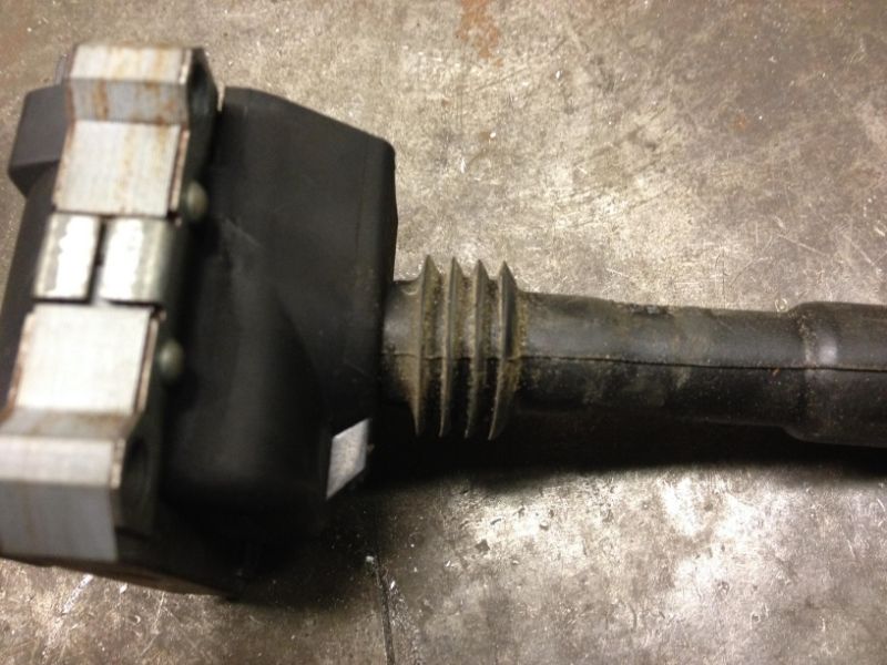
These motors are COP (Coil On Plug), no Dizzy or HT leads which I imagine is a good thing in the wet.
There are already quadruple seals on the stems as shown here but they'd take an O ring or two as well - to stop any wet getting into those deep plug holes.
The Alfa's Bosch COP's are 3 pin so they don't have inbuilt drivers to fire them directly from Megasquirt's spark signal outputs.
Think VW and some other makes are 4 pin and can be fired directly.
That's no big deal, just needs two spark boxes between Megasquirt and the COP's which Efi Extra have also supplied.
Some builders use Toyota Supra ones or similar. Either way, each fires 3 coils.
Last edited by nj111 on Wed Sep 02, 2015 12:53 pm; edited 2 times in total |
|
| Back to top |
|
|
nj111
Just got MTs
Joined: 15 Dec 2010
Odometer: 166
Location: Forest of Dean
|
| Posted: Thu Aug 28, 2014 1:21 pm Post subject:
|
|
|
There's a bigger problem in that Megasquirt does not control "fly by wire" electronic throttle bodies.
I guess that was worked by the original engine management system and with that removed it would need a control system to actuate it from the pedal signals.
In any case an Italian electronic throttle pedal and water are unlikely to mix well so it'll need to be changed for an old tech throttle body from the early / mid 90's worked off a cable with just butterfly valve and a basic 3 wire Throttle Position Sensor.
Like I said a while back "Alfas breath well" and the throttle body size confirms this because for a 2.5 litre motor it's a generous 70mm bore at it's smallest point - compare that to a 3 litre Porsche 968 at around 54mm.
This has made it tricky to find a replacement because almost everything else I've come across is way too small.
Ferrari 360 throttle bodies are 76mm bore and are often retrofitted to Alfa V6 motors, I think they plug straight in to the loom and without any other changes to the engine are claimed to improve torque, but they're also "fly by wire" so they don't solve this problem.
Eventually I found a possibility for £70, like the Ferrari one it's 76mm bore but from a 5 litre Porsche 928 S4.
As usual on this build, nothing is simple because Porsche V8 throttle bodies are integral with the plenum chamber.
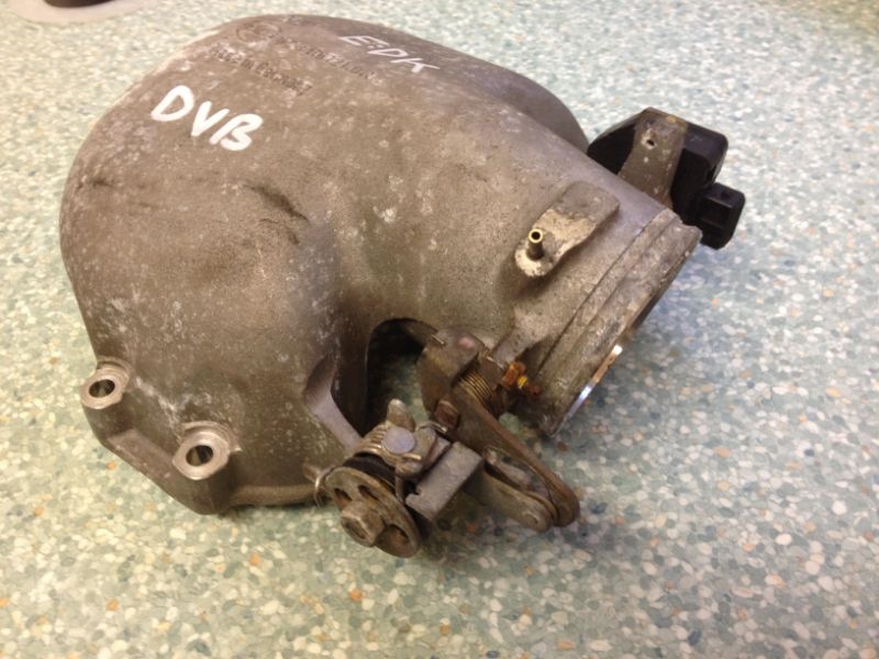
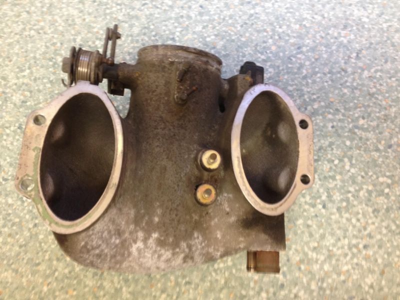
Some cutting, machining and welding is required, but the unit is spot on for quality even having needle roller bearings in the body for the butterfly valve shaft to rotate on.
Impressive and hence there's no wear to be found.
The butterfly valve mechanism is also neat, there's an inbuilt cam action giving fine control during the first part of the foot pedal movement then onto wide open throttle quite quickly.
Also twin return springs are built in.
Good work Mr Porsche.
Last edited by nj111 on Wed Sep 02, 2015 12:54 pm; edited 1 time in total |
|
| Back to top |
|
|
nj111
Just got MTs
Joined: 15 Dec 2010
Odometer: 166
Location: Forest of Dean
|
| Posted: Thu Aug 28, 2014 1:26 pm Post subject:
|
|
|
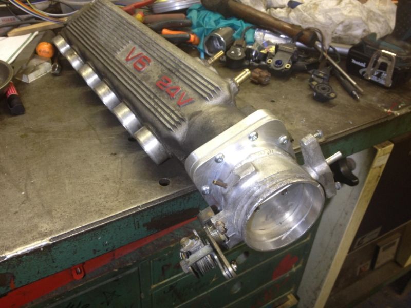
The Plenum chambers for Alfa's 2.5 and 3 litre engines are identical, the extra volume needed in the plenum for the larger 3 litre motor is gained by having larger bore induction pipes.
Those six chromed pipes being way bigger on the 3 litre motor.
These are the 2.5 ones.
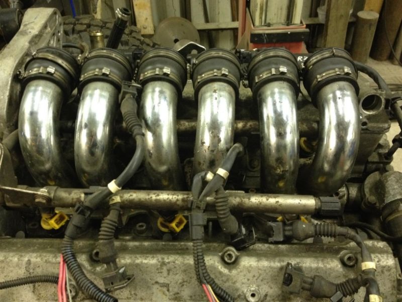
That means it's ok use the 2.5 litre plenum chamber on the 3 litre engine.
I could have TIG welded the throttle body to the plenum, then eventually moved the whole lot to the larger motor.
But I didn't feel comfortable with that and would prefer to be able to remove the throttle body or if there are any problems be able to try a different one.
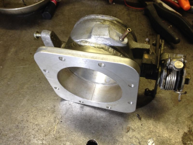
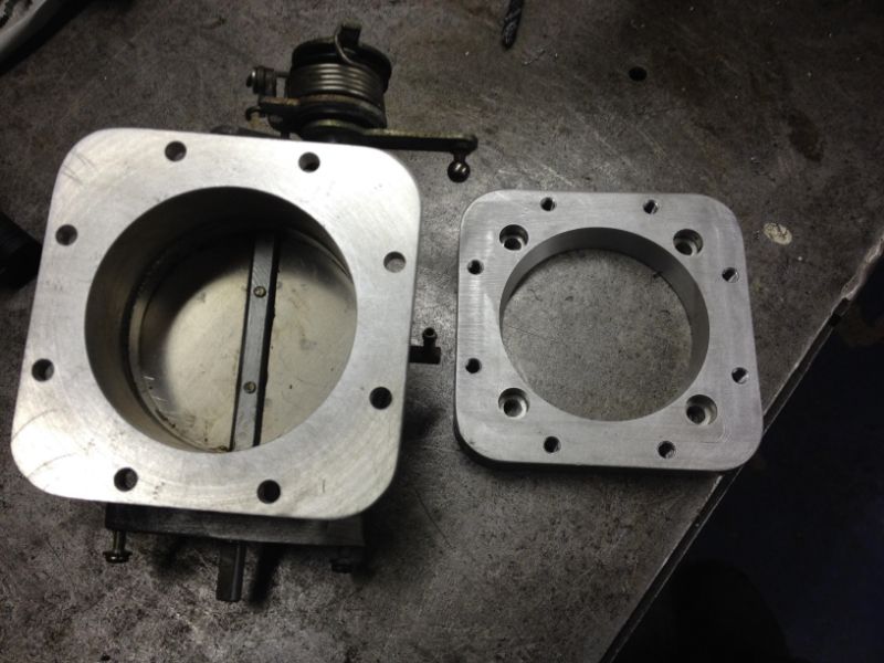
In short, I've spun up a flange for it and welded that to the throttle body, then made an adaptor plate to fit it to the plenum chamber.
Took 2 evenings used up a few offcuts and went something like this:
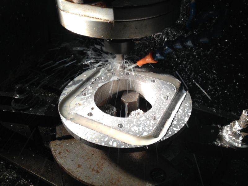
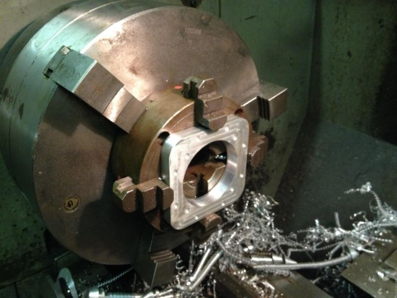
Chop Porsche throttle body through on the Bandsaw
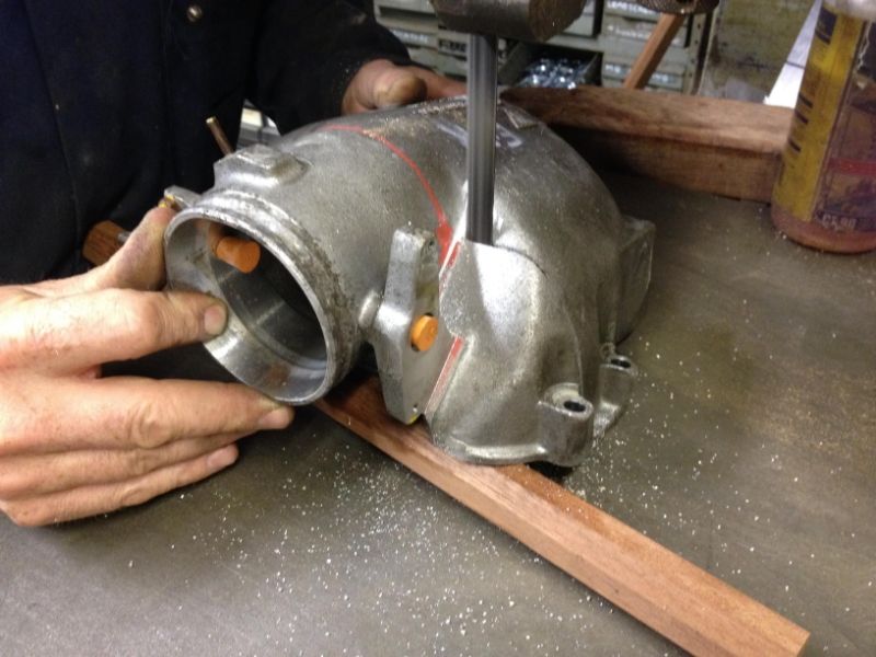
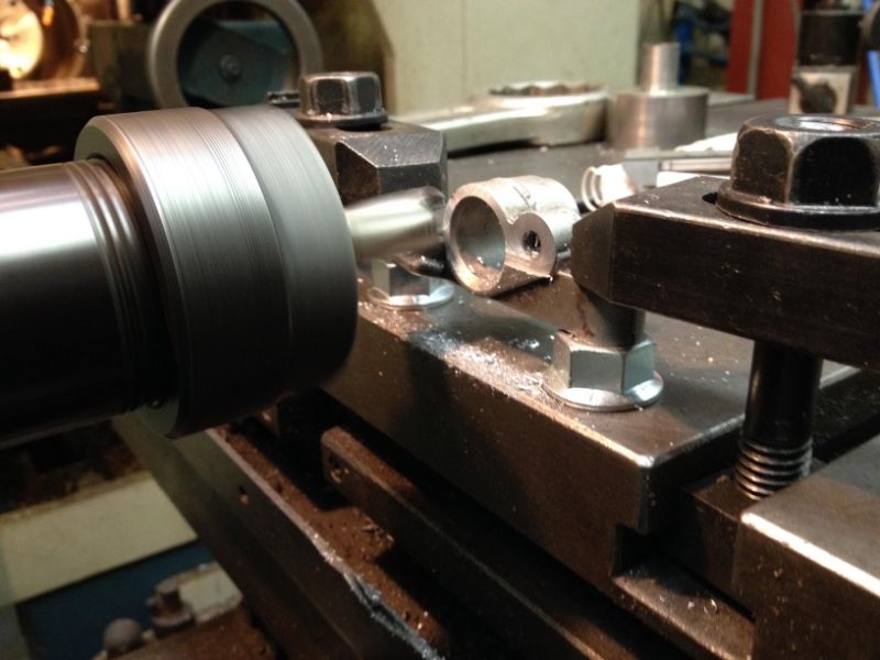
Leaving an odd shape, more cutting and welding required, followed by a skim in the lathe.
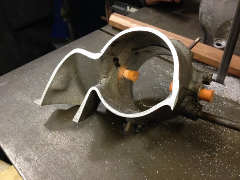
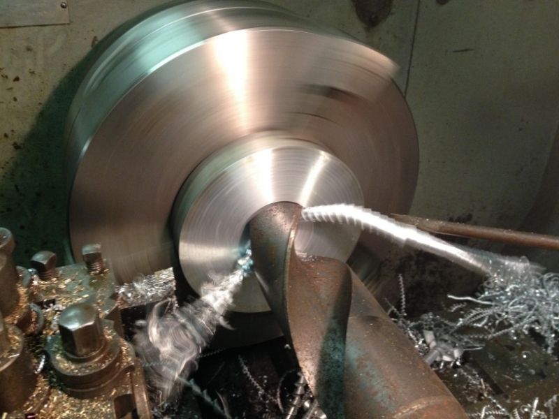
Welded bits in where missing from the circular body and skimmed true
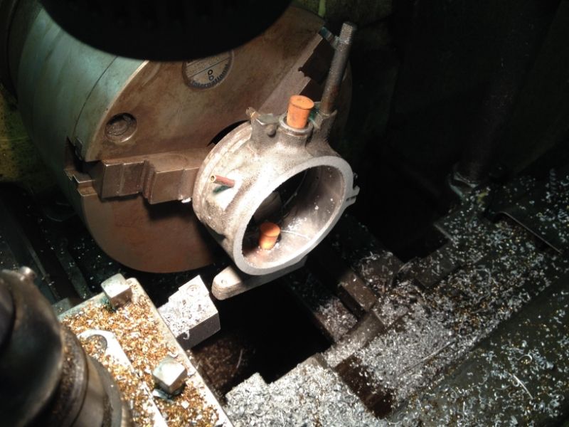
This flange will be welded to the throttle body. Whacked a 66mm drill straight through then bored out to size.
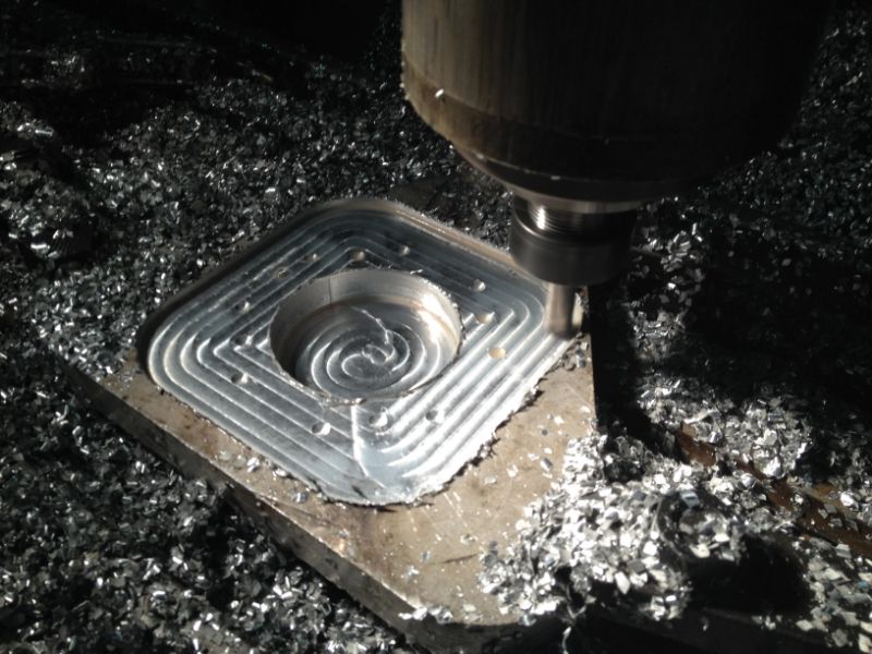
Move to mill, spot hole centres and Mill to shape.
The other part is an adaptor plate milled from an offcut of ally plate which ends up 14mm thick.
Last edited by nj111 on Wed Sep 02, 2015 12:55 pm; edited 1 time in total |
|
| Back to top |
|
|
nj111
Just got MTs
Joined: 15 Dec 2010
Odometer: 166
Location: Forest of Dean
|
| Posted: Thu Aug 28, 2014 1:32 pm Post subject:
|
|
|
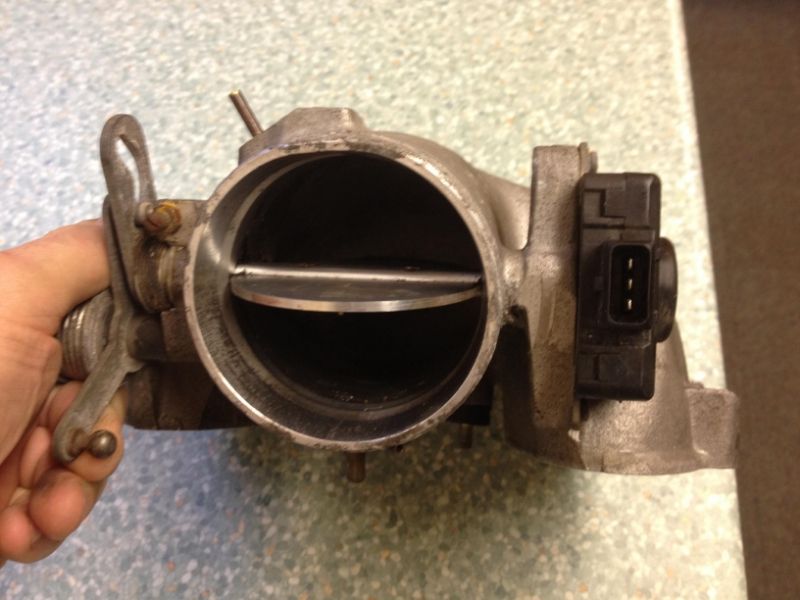
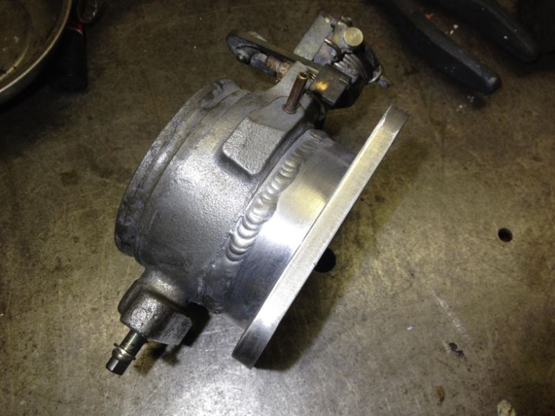
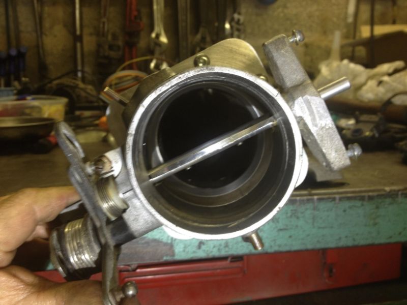
End result
Big hole.
The Bosch Throttle Position Sensor was full of water and they're having a laugh with the price of a replacement (downside of Porsche name),
so I've bought an almost identical one as fitted to a variety of small modern cars (Peugeot / Alfa etc) and fitted that. Price £10, it's only a potentiometer that's plenty to pay for one of those.
Any 3 wire TPS that rotates the right way will do as it's properties are configured in Megasquirt. At that price we'll carry a spare.
Next, I need to get the engine running, the plan is to temporarily install the following in a very basic lashed up manner:
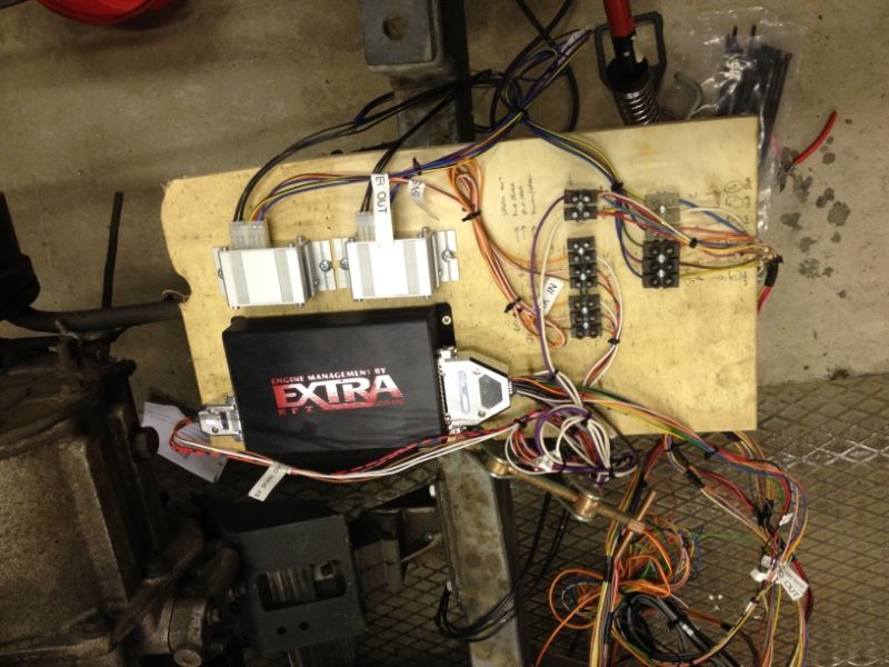
Megasquirt MS2 - daughter's turn to do some wiring and neat it is too.
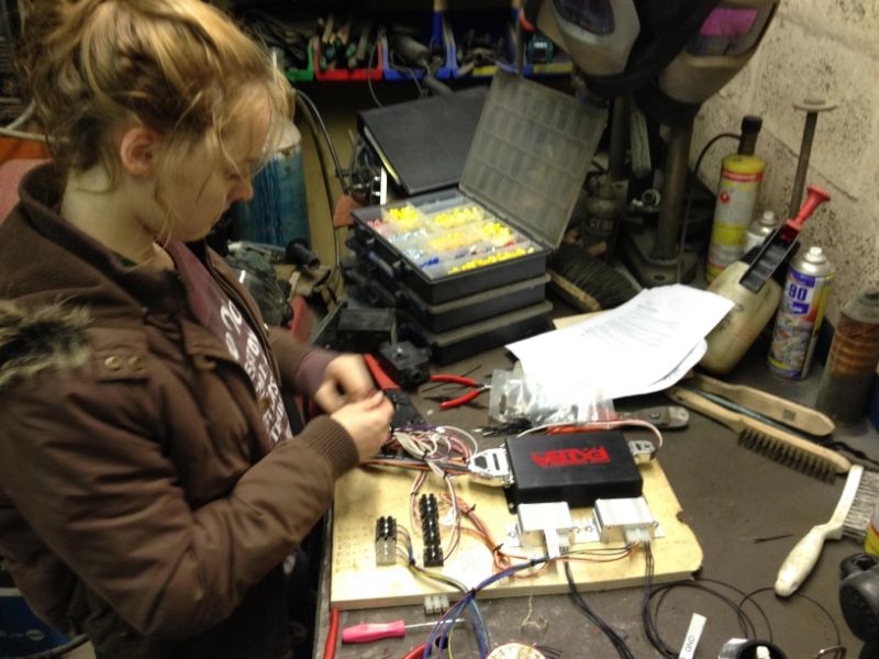
Here MS2 fixed to a bit of ply and clamped to the chassis but that's ok for now. The silver boxes are the two Sparkboxes each fires 3 coils.
That's about it for now, next I'll fit the original Alfa fuel system, fuel tank, pump, flow and return hoses.
With the exception of the fuel pump, which is matched for pressure and flow, the rest will be junked later.
An exhaust system with the original 4 wire heated Lambda Sensor.
Temporary coolant system.
Hopefully be able to run the engine and set up fuel / ignition mapping as best I can, given that I can't drive it under load yet.
Thanks for looking, back soon.
Last edited by nj111 on Wed Sep 02, 2015 12:56 pm; edited 1 time in total |
|
| Back to top |
|
|
Twiss
Mud Obsessed
Joined: 18 Feb 2008
Odometer: 6438
Location: Birkirkara, Malta
1993 Suzuki Samurai
|
| Posted: Thu Aug 28, 2014 2:17 pm Post subject:
|
|
|
Looking good, and glad to see an update!
I will probably be going megasquirt on my Samurai, but with the standard vitara 16v injection system
I will be interested to see how many issues you have with it 
__________________________________
Twiss
'95 Samurai 416 16v
'92 Maruti Gypsy MG410
www.suzukiclubuk.co.uk |
|
| Back to top |
|
|
nj111
Just got MTs
Joined: 15 Dec 2010
Odometer: 166
Location: Forest of Dean
|
| Posted: Mon Sep 15, 2014 4:05 pm Post subject:
|
|
|
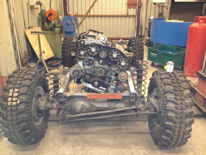
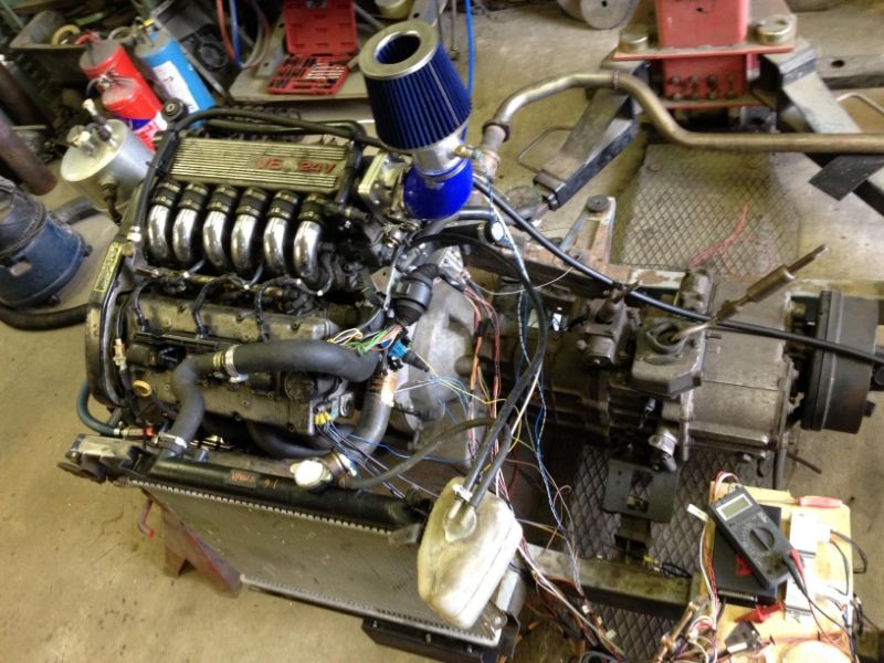
Looking basic without axles
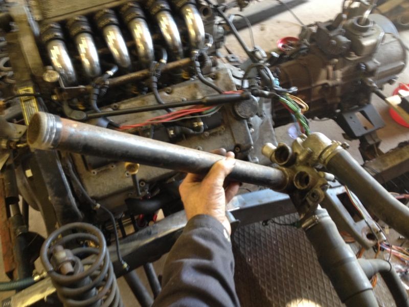
These motors have the thermostat housing at the back and a steel tube sealed with O rings running up the valley to the front mounted water pump.
That should work out well for mounting a rad in the rear of the truck, as there's no water pipes in front of the motor.
That pipe is a pig to refit when it's got new O rings on it though. Had to use hydraulic ram to push it back in place.
Note to self, leave access plate in bulkhead incase I need to get the pipe out!
All ECU wiring connected and fused as it should be, but everything else thrown together from whatever was lying about.
Will not use this Vitara rad in the build but it's ok here mounted side saddle for a test bed.
The exhaust is 20 feet long and running out of the door. As soon as I'm satisfied it runs ok that's all coming off.
Last edited by nj111 on Wed Sep 02, 2015 12:57 pm; edited 1 time in total |
|
| Back to top |
|
|
nj111
Just got MTs
Joined: 15 Dec 2010
Odometer: 166
Location: Forest of Dean
|
| Posted: Mon Sep 15, 2014 4:09 pm Post subject:
|
|
|
A bit about Megasquirt:
With any Megasquirt installation Grounding is critical, and there are quite a few grounds running from the ECU and other sensors.
These must all be run as separate cables to one place on the engine block otherwise you get all sorts of ground loop currents which will mislead the ECU big time.
All 37 pins on the Megasquirt connection check out for voltage and resistance within spec. Those checks are done before plugging the connector into the ECU.
It's all clearly explained in Phil's instructions. Very sensible approach to check all that out before plugging in to the ECU.
The tuning software (Tuner Studio) provided is used to communicate with the ECU. Already I've found it's handy to be able to ask for help.
- my fault for having MS2 in stock for nearly 3 years so the latest comms software was looking for an ECU with different firmware.
Anyhow, Phil at Efi Extra always responds to any questions - that's worth a lot so the matter was resolved in a few minutes.
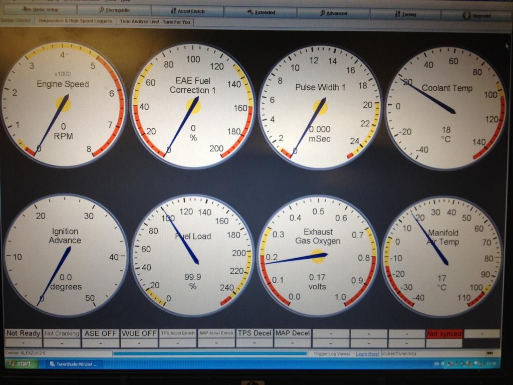
Result! Laptop and ECU talking to each other. Air Temp / Water Temp and Lambda have plausible output signals. Crank pos sensor also gives a readout whilst cranking.
Don't know about other suppliers but if you order Megasquirt from Efi Extra, Phil will ask what motor it's going on and load the ECU with settings good enough to get you started, including a basic fuel and ignition map
- that may or may not be adequate to actually start the motor but will be close.
I still went through the manual and read up on all those but having all these configured by someone that has a knowledge is a massive help.
There were some things I had to tweak, for example on these motors at TDC on Cyl 1 the crank sensor is positioned 17 teeth (96 degrees) after the first gap tooth in the 60/2 sensor ring and obviously MS2 needs to know about that.
This is a setting that will be fine tuned with a timing light, but that calc is close enough for initial start up.
The original crank sensor is VR type (variable reluctance) and that's just fine for MS. It's a 3 wire device, one signal, one ground and one shield.
If the signal from this is too weak there are two Pots that can be adjusted on the MS board.
When MS sees an input from the crank sensor (i.e. crank rotating) it enables the fuel pump relay. It's recommended that ignition coils and injectors are also wired through the fuel pump relay, otherwise they will be live all the time the ignition is on.
So nothing happens without this signal from the crank sensor!
This signal played me up a bit though. Checked its output with an oscilloscope and it looked good - an A.C. waveform of about 5 volts, whichever way it was connected.
Initially engine started okay but revs readout on the laptop was erratic and motor wouldn't rev beyond idle.
Swapped the signal wires around from Crank sensor and that was way better, motor revved freely,as the manual says it does matter which way these two wires are connected.
That was looking good for a while but a few minutes later wouldn't start at all because had lost the crank signal!
Adjusted the pots on MS board but that didn't help.
Checked sensor gap against the 3 litre motor. Found problem. Sensor too far from the ring it reads. There was a 1.4mm gap, needs to be 0.8mm. My fault as it's dowelled to the sump in slightly the wrong place. Engineering error.
Luckily the sensor fits into a small casting, so was able to machine 0.7mm off the face of that on the Kearns to get it where back it should be.
That's solved the problem and now there's a reliable output all the time.
I've not messed with fuel or ignition mapping yet as the thing runs brilliantly but of course it's off load.
Other than TDC there are no timing marks on the front pulley, I guess they don't bother with those these days as there's no dizzy and timing is permanently set by the ECU. Not something that is meant to be altered.
But in MS timing needs to be set up so I'll need to figure out some appropriate advance settings.
Oil pressure is 100 psi so will need to play with the bypass setting on the pump. With all those scavenge pumps (four) there are some oil venting issues from the top of the tank, there's so much return (oil and air) flow that some oil is coming out of the vent pipes. I expect the crankcase has negative pressure, which will be fine. A lot of people get this issue with dry sumps, maybe needs a small vent tank with return, will look into that, hopefully will be resolved somehow.
Not done anything yet about fast idle when cold, will leave that until the end of the build. The mixture will already have been enriched by Megasquirt.
There are a number of options, including doing nothing, i.e. just rev a bit or fit a fast idle solenoid which simply overrides the throttle stop, or go for a modern fast idle valve 2 wire / 3 wire or 4 wire (stepper motor).
Expect I'll keep it simple and stick a solenoid on there. I can understand those better.
Getting the motor running has been a diversion but I needed to know all was good so when I revisit it at the end of the project hopefully there's no major unforeseen issues.
When it can be driven there will be a good few hours spent fine tuning and maybe a rolling road is the way forward, but for now it looks very promising.
Finally we have a working motor and transmission in a chassis so from here it's pretty much a standard build.
Last edited by nj111 on Wed Sep 02, 2015 1:02 pm; edited 1 time in total |
|
| Back to top |
|
|
teamidris
Mud Obsessed

Joined: 24 Feb 2008
Odometer: 3372
Location: Staffordshire UK

|
| Posted: Mon Sep 15, 2014 6:31 pm Post subject:
|
|
|
Fascinating write up
I couldn't see how to do the breather so I linked the rocker boxes together and set off to the tank. Then a second T in that 1/2" pipe is the breather. I figured gas can go around and around as much as it likes and any excess comes out the second T. Then I haven't got to worry if there is a sump or seal leak while under water aided by a vacuum. (If it was a tarmac racer I'd run the vacuum sump for sure).
__________________________________
https://m.youtube.com/channel/UC3l3zoaCabKrgBSULSV1YgA |
|
| Back to top |
|
|
teamidris
Mud Obsessed
Joined: 24 Feb 2008
Odometer: 3372
Location: Staffordshire UK
|
| Posted: Mon Sep 15, 2014 6:35 pm Post subject:
|
|
|
David Lazenby said to make sure you don't get pressure in the tank as it holds the bubbles in. Or, to reverse the scenario, if you could have a vacuum in the tank it would pull the gas from the oil. The bloke is a gold mine of info
__________________________________
https://m.youtube.com/channel/UC3l3zoaCabKrgBSULSV1YgA |
|
| Back to top |
|
|
|
|
|
|
You cannot post new topics in this forum
You cannot reply to topics in this forum
You cannot edit your posts in this forum
You cannot delete your posts in this forum
You cannot vote in polls in this forum
You can post calendar events in this forum
|
|
|


